Very simple FM transmitter 85-108Mhz
In my early teens, experimenting with circuits, I remember building an FM transmitter following
data I read about the varicap effect of semiconductor junctions. I expected to see a varicap
effect on the C-B junction of a biploar transistor. To harness and prove this, I made the transistor
oscillate in the FM band, then injected an AF voltage on the collector to vary the C-B junction
capacitance, and thereby modulating the oscillator frequency.
 The choice of components is based on what I had in my hobby box at the time.
A 2N3904 may perform better than a BC550B in this application.
You may want to add a trimmer capacitor in place of C3 to allow the circuit to be tuned.
I have found that without an antenna, it will broadcast 30M through walls, in a noisy radio environment.
The choice of components is based on what I had in my hobby box at the time.
A 2N3904 may perform better than a BC550B in this application.
You may want to add a trimmer capacitor in place of C3 to allow the circuit to be tuned.
I have found that without an antenna, it will broadcast 30M through walls, in a noisy radio environment.
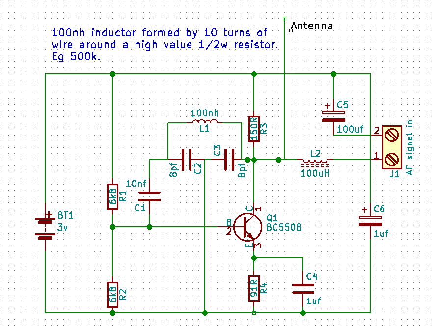
Principle of operation
L1, C2 and C3 form a tank circuit in a colpitts oscillator configuration. C4 forms a low AC emitter load for the transistor.
R1, R2, R3 and R4 create a DC biasing network, holding the transistor out of saturation, and at a current close to optimal gain. Vc > Vb > Ve.
L2 isolates the AF signal from the RF signal, and from the tank circuit. C5 blocks DC from the audio input.
C1, C4 and C6 are simply coupling and decoupling capacitors. Their values aren't too critical. Low inductance ceramic will work well.
The capacitances around the transistor very much form part of the tank circuit. As the voltages accross the
transistor vary, the value of the capacitance changes, which in turn changes the tank circuit capacitance. About 100mv audio
signal will generate maximum modulation for most radio receivers.
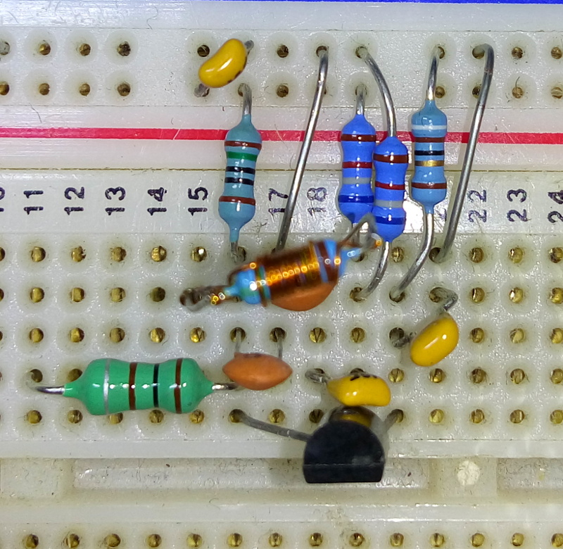
Since I built this on a breadboard with plenty of stray capacitance, your mileage may vary. Most notably, you may need different values for
C2 and C3 as these are close to the stray capacitances you may find between connection strips in a breadboard. Additonally, at these frequencies,
small wire loops may generate significant inductive reactance. I used a high value half watt resistor as an inert former for the
inductor. 10-11 turns of enamel copper wire give the required inductance of about 100 nanoHenry. Any similarly sized resistor over 10K
should work fine. I used 5.9Megohm.
I used my mobile phone earphone output for the AF signal. I found the received signal quality to be pretty good fidelity.